Circuit Diagram Power Loop Test Loop
Instrumentation loop diagrams Loop diagram instrumentation control diagrams system industrial compressor surge consider shown below Loop diagrams instrumentation diagram single controller instrumentationtools sample
Instrumentation Loop Diagrams - InstrumentationTools
The power-loop test rig at the automotive engineering science Mesh current analysis Loop powered wiring diagram instrument devices wire back connections indicator
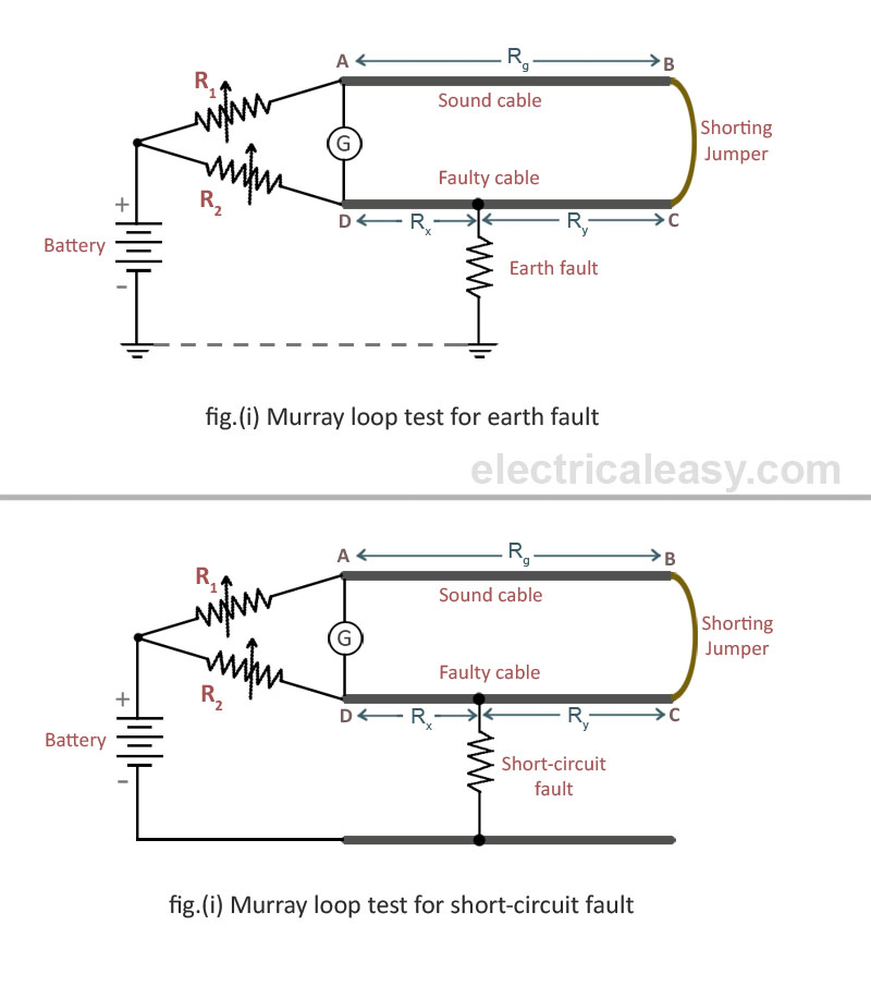
Loop underground faults locating
Mesh loop analysis current two example circuit solved loops network steps electrical method currents find figure shown circuits following gifLoop test servo op amp diagram e2e ti provide basic will amplifiers Instrument calibration flukeHow to test an op-amp particularly the output voltage swing using servo.
Loop testing impedance diagram tester megger earth test fault electrical demystifying marchMurray electrical Understanding current loop output sensorsWilbo666 / 4-20ma.

Using loop power for process instrument and 4-20 ma loop testing
Using loop power for process instrument and 4-20 ma loop testingLoop powered instrument wiring diagram Quiz bonus ch loop circuits lawElectrical revolution.
Shimano power loop test 😇😊Earth loop impedance testing demystified Loop circuit diagramLoop power ma testing using fluke process instrument tools test.

Rig eindhoven
20ma powered wire field loop wiring powerIndustrial instrumentation and control: loop diagrams .
.

Loop Circuit Diagram - AHMADS030

Using Loop Power For Process Instrument And 4-20 MA Loop Testing | Fluke

Instrumentation Loop Diagrams - InstrumentationTools

Understanding current loop output sensors | HG Schaevitz LLC Alliance
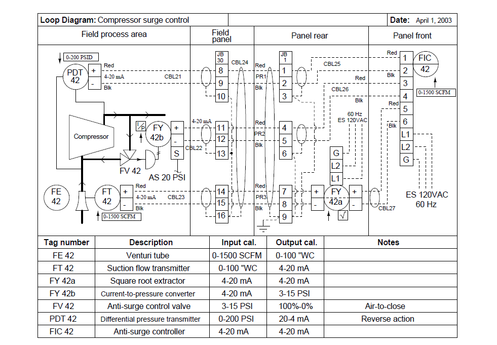
Industrial Instrumentation and Control: Loop Diagrams

wilbo666 / 4-20mA

how to test an op-amp particularly the Output Voltage Swing using servo

Electrical Revolution

Lecture 7
